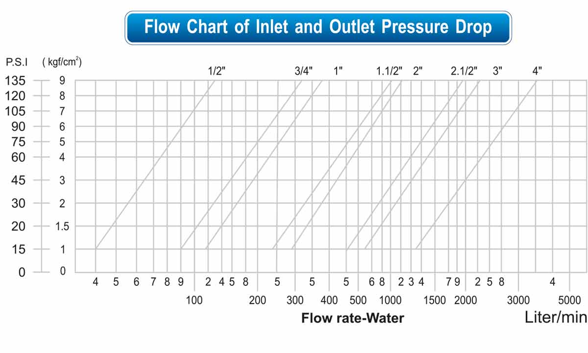
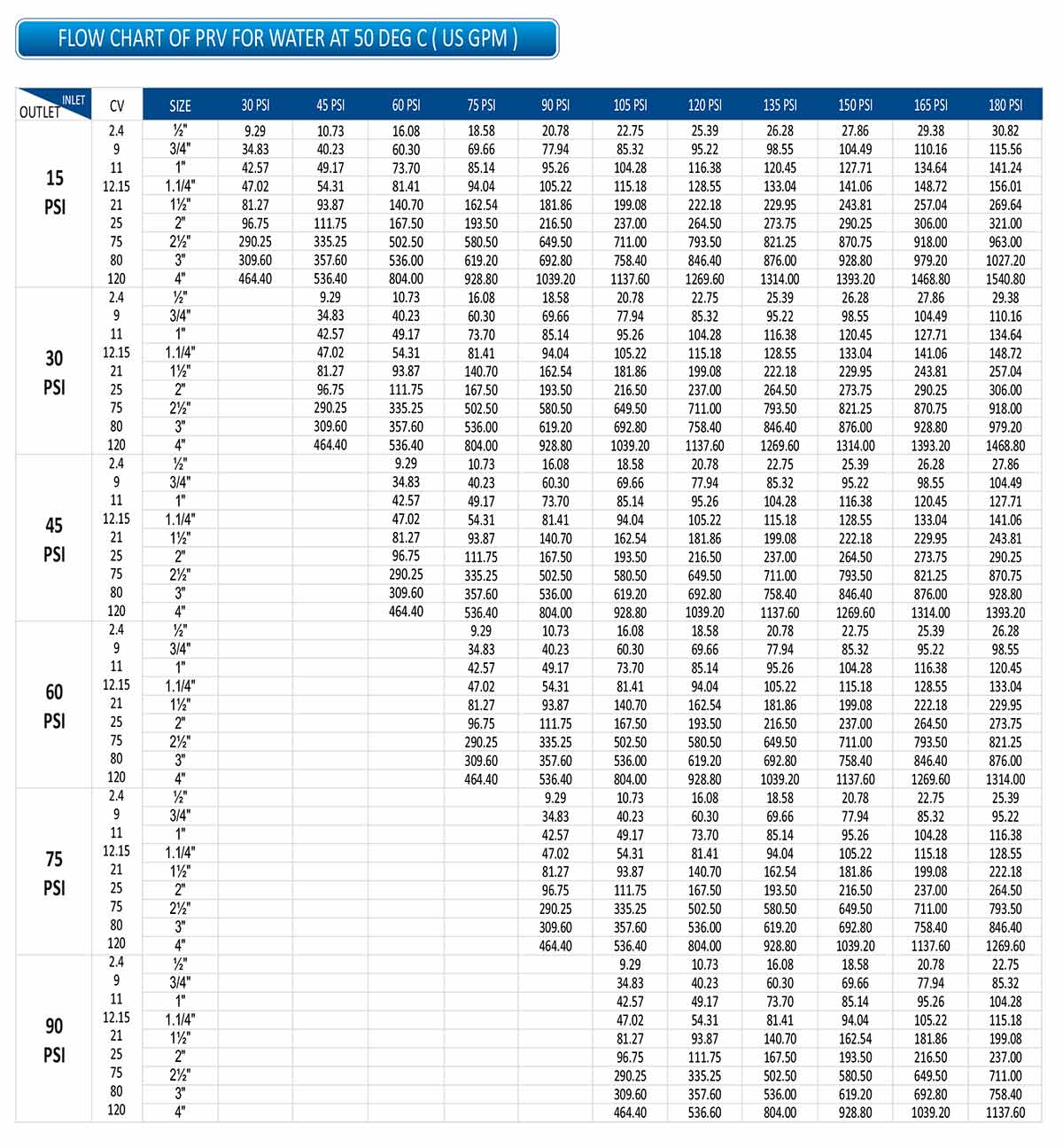
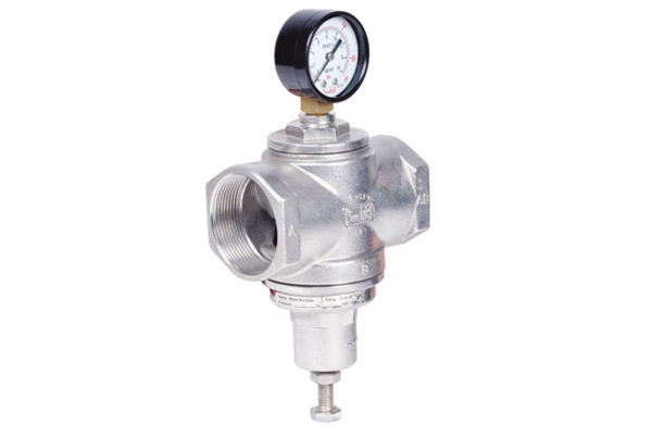
“4Matic” Offer Pressure Reducing Valve Investment Cast Stainless Steel Material for Air, Water, Oil, Gas, Steam & Chemicals.
Size Range : 1/2″ to 4″ Screwed / Flange End
Standard
- 1/2″ to 4″ Meet requirements of
- ASSE Standard 1003. ( ANST 112.26 )
- CSA Standard B356
- ( ASSE – American Society of Sanitary Engineering )
- ( CSA – Canadian Standard Association )
Pressure / Temperature |
|
| Temperature | 80°C (For Water) |
| Maximum Working Pressure | 21 Kg/cm2, Inlet |
| Pressure Adjusting Range | 1 ~ 6 Kg/cm2, 4 ~ 10 Kg/cm2 8 ~ 13 Kg/cm2, 12 ~ 20 Kg/cm2 20 ~ 35 Kg/cm2 |
Options
- Available different Models for Air, Water, Oil, Gas, Steam & Chemical
- LP – Low Pressure Range : 10 – 35 PSI
- n HP – High Pressure Range :
– Max. Inlet 40 Kg/cm2
– Outlet 12 ~ 25 Kg/cm2 20 ~ 35 Kg/cm2
Example
- Pressure drop needed for fully – opened valve. gate for adjustable Pressure range 3 ~ 9 Kg/cm2 of direct activated pressure reducing valve
- A = B / 4 = 9 – 3 = 1.5 Kg/cm2
- If the setting pressure of outlet 6 Kg/cm2, Pressure of fully – opened valve gate will be P = 6-1.5 = 4.5
- Kgf/cm2 (Outlet Pressure should go down under 4.5 Kg/cm2 to make valve gate fully open )
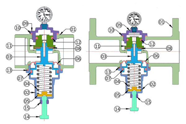
| No. | Description | Material | Qty. |
| 01 | Body | CF8 / CF8M | 01 |
| 02 | Bonnet | CF8 / CF8M | 01 |
| 03 | Piston | CF8 / CF8M | 01 |
| 04 | Spring | S. S. 302 | 01 |
| 05 | Spring Guide | Brass / S. S. 410 | 01 |
| 06 | Diaphragm | NBR / Viton | 01 |
| 07 | Piston V – Seal | NBR / Viton | 01 |
| 08 | Washer | NBR / Viton | 01 |
| 09 | End Cover | CF8 / CF8M | 01 |
| 10 | End Cover ‘O’ – Ring | NBR / Viton | 01 |
| 11 | Plug | CF8 / CF8M | 01 |
| 12 | Plug V – Seal | NBR / Viton | 01 |
| 13 | Bonnet ‘O’ – Ring | NBR / Viton | 01 |
| 14 | Adjusting Bolts | S. S. 304 / 316 | 01 |
| 15 | Adjusting Nut | S. S. 304 / 316 | 01 |
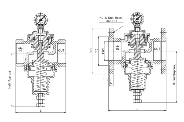
| Dimensions : (Screwed End) (All Dimensions are in mm) | ||||||
| Valve Model | Valve Size | L | H | CV | Weight Approx. | |
| MM | Inch | |||||
| 4M-WGS-15-SD | 15 | 1/2″ | 70.5 | 72 | 24 | 0.800 |
| 4M-WGS-20-SD | 20 | 3/4″ | 85.5 | 87 | 9 | 1.000 |
| 4M-WGS-25-SD | 25 | 1″ | 90.5 | 91 | 11 | 1.000 |
| 4M-WGS-32-SD | 32 | 1.1/4″ | 98.5 | 100 | 12.15 | 1.200 |
| 4M-WGS-40-SD | 40 | 1.1/2″ | 115 | 116 | 21 | 2.250 |
| 4M-WGS-50-SD | 50 | 2″ | 120 | 120 | 25 | 2.400 |
| 4M-WGS-65-SD | 65 | 2.1/2″ | 148 | 147 | 75 | 7.650 |
| 4M-WGS-80-SD | 80 | 3″ | 177 | 176 | 80 | 8.050 |
| 4M-WGS-100-SD | 100 | 4″ | 190 | 190 | 120 | 12.500 |
| Dimensions : (Flange End) (All Dimensions are in mm) | |||||||||||||
| Valve Model | Valve Size | Port | ØD | b | Øg | f | ØJ | N | PCD | L | H | Weight Approx. |
|
| MM | Inch | ||||||||||||
| 4M-WGF-15-FD | 15 | 1/2″ | 12.5 | 88.9 | 8.9 | 35.05 | 2 | 15.75 | 4 | 60.45 | 138 | 100.8 | 1.500 |
| 4M-WGF-20-FD | 20 | 3/4″ | 17 | 98.55 | 8.9 | 42.9 | 2 | 15.75 | 4 | 69.85 | 147 | 111.1 | 2.000 |
| 4M-WGF-25-FD | 25 | 1″ | 24 | 107.9 | 9.6 | 50.8 | 2 | 15.75 | 4 | 79.25 | 127 | 87.7 | 2.250 |
| 4M-WGF-32-FD | 32 | 1.1/4″ | 30 | 117.34 | 11.1 | 63.5 | 2 | 15.75 | 4 | 88.9 | 170 | 108.8 | 3.100 |
| 4M-WGF-40-FD | 40 | 1.1/2″ | 37 | 127 | 12.6 | 73 | 2 | 15.75 | 4 | 98.55 | 195 | 137.5 | 4.700 |
| 4M-WGF-50-FD | 50 | 2″ | 49 | 152.4 | 14.15 | 91.95 | 2 | 19.05 | 4 | 120.65 | 208 | 138.5 | 6.300 |
| 4M-WGF-65-FD | 65 | 2.1/2″ | 64 | 177.8 | 15.4 | 104.65 | 2 | 19.05 | 4 | 139.7 | 210 | —- | 13.500 |
| 4M-WGF-80-FD | 80 | 3″ | 80 | 192.5 | 17.9 | 129.16 | 2 | 19.05 | 4 | 152.4 | 225.5 | —- | 14.500 |
| 4M-WGF-100-FD | 100 | 4″ | 100 | 230.6 | 22.4 | 158.57 | 2 | 19.05 | 8 | 190.5 | 251 | —- | 24.600 |
