Check Valve PN16
PN16 Cast Iron Swing Check Valve, Lever & Weight Model: 4M-SWC
Feature
• Pressure Ratings PN16
• Model: 4M-SWC are manufactured and tested per requirements AWWA C508 standard for swing-check valves for waterworks service
• Drilling flange: ANSI B16.1 Class 125 / ANSI B16.1 Class 250
• Corrosion Protection: Standard epoxy painting system with overall coating thickness 250m according to AWWA C550
• All fasteners are Stainless Steel type 304
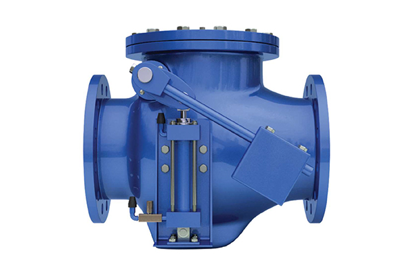
Optional Devices
Closure Control Devices code as follows:
- AC Air Cushion Side Mounted Cylinder (Lever & Weight)
- OC Oil Controlled Side Mounted Cylinder
Closure Control Devices
Air Cushion Side Mounted Cylinder(AC)
The Cast Iron Swing check valve Lever & Weight Model: 4M-SWC with Air Cushion Side Mounted Cylinder (AC) Device is designed to handle higher flow rates, pressures and withstand shock.
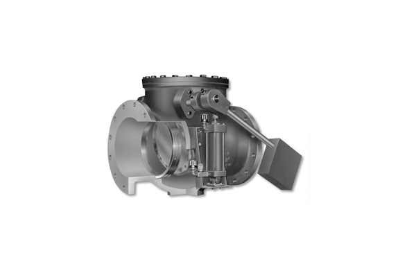
Application: For Free Open, Fast Close applications, the air-cushioned check valve utilizes a totally enclosed cushion cylinder externally mounted to the side of the main valve body. A heavy outside lever positively clamped to an extra-large diameter pivot shaft, forces the disc to close immediately upon pump shut down and before reverse flow takes place. The weighted lever drives the piston into the cushion chamber, compressing the 30 trapped air and creating a cushion during valve closure.
Closure Control Devices
Oil Controlled, Side Mounted Cylinder(OC)
The Cast Iron Swing check valve Lever & Weight Model: 4M-SWC with Oil Controlled, side mounted Cylinder (OC) Device is designed to handle higher flow rates, pressures and withstand shock.
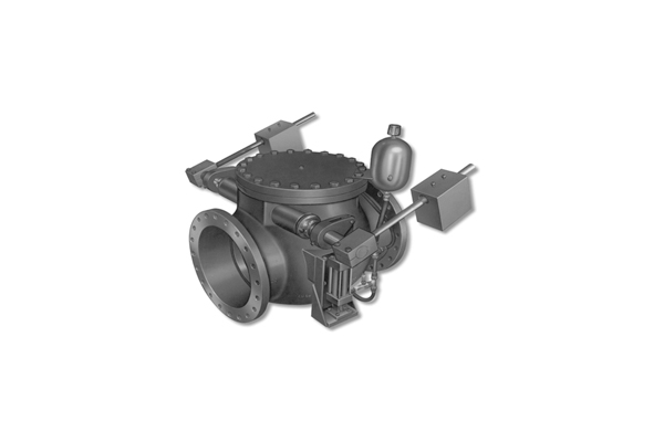
Application: For Free Open, Slow Close applications, The Cast Iron Swing check valve Lever & Weight Model: 4M-SWC are available with an Oil Controlled, Side Mounted Cylinder closure control device. The totally enclosed oil cylinder is protected from the elements. Three-stage closure on valves minimizes damaging water hammer.
Valve Assembly Drawing Layout
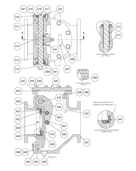
Valve Assembly Parts Identification
| A01 | BODY |
| A02 | COVER |
| A03 | COVER SEAL |
| A04 | COVER BOLTS |
| A05 | BODY SEAT RING |
| A06 | DISC SEAT |
| A07 | DISC STOP |
| A08 | DISC PIN |
| A09 | DISC ARM |
| A10 | DISC |
| A11 | PIVOT SHAFT STRAIGHT BUSHING |
| A12 | PIVOT SHAFT FLANGED BUSHING (ALL EXCEPT 42”) |
| A12 | SPACER (42” ONLY) |
| A13 | PIVOT SHAFT |
| A14 | DISC ARM SET SCREW |
| A15 | PIVOT SHAFT COVER |
| A16 | PIVOT SHAFT COVER BOLT |
| A17 | PIVOT SHAFT SEAL |
| A18 | PIVOT SHAFT COVER SEAL |
| A31 | SEAT RETAINING RING |
| A32 | SEAT RETAINING SCREW |
| A33 | PIVOT SHAFT KEY |
| A37 | PIVOT SHAFT SEAL RETAINER |
| A39 | DISC STOP LOCKNUT |
| A40 | BODY SEAT RETAINING SET SCREW |
| A41 | DISC PIN RETAINER |
| A42 | COVER PIPE PLUG |
| A43 | BODY SEAT SEAL |
| A53 | PIVOT SLEEVE BEARING |
| A57 | DISC ARM SLEEVE |
| A60 | PIVOT SHAFT COLLAR |
| A61 | PIVOT SHAFT SET SCREW |
| A65 | COVER NUT |
| A66 | DATA PLATE |
| A67 | DRIVE SCREW |
| A90 | BODY PIPE PLUG |
| A91 | DISC RING SEAL |
| A92 | PLUG |
| A93 | PLUG SEAL |
| A95 | PLUG RETAINING SCREW |
| A96 | COVER BOLT WASHER |
| A97 | PIVOT SHAFT COVER WASHER |
| A98 | COVER WASHER |
| A99 | DISC STOP WASHER |
Valve Assembly with Oil Controlled,
Side Mounted Cylinder(OC)
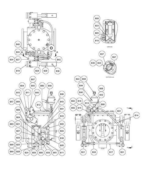
Valve Assembly with Oil Controlled,
Side Mounted Cylinder(OC) Parts Identification
| B01 | NIPPLE |
| B02 | TEE |
| B03 | NIPPLE |
| B04 | PIPE PLUE |
| B05 | TEE |
| B06 | REDUCING BUSHING (SEE NOTE 3) |
| B07 | CROSS |
| B08 | NIPPLE |
| B09 | HOSE |
| B10 | TEE |
| B11 | NIPPLE |
| B12 | HOSE |
| B13 | CROSS |
| B14 | HOSE |
| B15 | TIMING VALVE SCREW |
| B16 | TIMING VALVE NUT |
| B17 | HOSE |
| B18 | NIPPLE |
| B19 | COUNTERWEIGHT LEVER ARM |
| B20 | PNEUMATIC CYLINDER |
| B21 | CYLINDER BRACKET MOUNTING BOLT |
| B22 | UNION |
| B23 | PIPE PLUG |
| B24 | CYLINDER BRACKET |
| B25 | CYLINDER BRACKET MOUNTING BOLT |
| B26 | CYLINDER BRACKET MOUNTING NUT |
| B27 | CYLINDER LEVER |
| B28 | COUNTERWEIGHT ARM |
| B29 | COUNTERWEIGHT |
| B30 | FLOW CONTROL VALVE |
| B31 | ELBOW |
| B32 | NIPPLE |
| B33 | TIMING VALVE CAM DIAL |
| B34 | CUSHION LEVER KEY |
| B35 | CUSHION LEVER SET SCREW |
| B36 | COUNTERWEIGHT SET SCREW |
| B37 | DRIVE SCREW |
| B38 | ELBOW |
| B39 | CAM SET SCREW |
| B40 | OIL RESERVOIR TANK |
| B41 | ELBOW |
| B42 | NIPPLE |
| B43 | HOSE |
| B44 | PIPE PLUG (SEE NOTE 2) |
| B45 | TIMING VALVE |
| B46 | TIMING VALVE MOUNTING BRACKET |
| B47 | CAM |
| B49 | LEVER ARM KEY (NOT SHOWN) |
| B55 | LEVER ARM BOLT/SET SCREW |
| B56 | LEVER ARM NUT |
| B57 | WASHER |
| B58 | AIR BREATHER |
| B59 | THREADED ROD (SEE NOTE 1) |
| B60 | HEX NUT (SEE NOTE 1) |
| B61 | NIPPLE |
| B62 | WASHER |
| B63 | WASHER |
| B64 | WASHER |
NOTES
1. B59 & B60 ARE REPLACED WITH A SINGLE BRACKET (NOT SHOWN) WHEN VALVE IS USEDIN VERTICAL ORIENTATION
2. VALVE IS SHIPPED WITH PIPE PLUG IN PLACE OF BREATHER ON RESERVOIR, BREATHERSHIPPED LOOSE
3. ADDITIONAL REDUCER ON 14-20” IS USED TO CONNECT OIL RESERVOIR TO 1” NPT CROSS
Valve Assembly with Air Cushion Side Mounted Cylinder(AC)
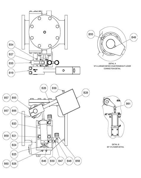
Valve Assembly with Air Cushion Side Mounted Cylinder(AC)
Parts Identification
| B19 | COUNTERWEIGHT LEVER ARM |
| B20 | PNEUMATIC CYLINDER |
| B21 | CYLINDER BRACKET MOUNTING BOLT |
| B24 | CYLINDER BRACKET |
| B25 | EYE BRACKET MOUNTING BOLT |
| B26 | EYE BRACKET MOUNTING NUT |
| B27 | CUSHION LEVER |
| B28 | COUNTERWEIGHT ARM |
| B29 | COUNTERWEIGHT |
| B30 | FLOW CONTROL VALVE |
| B34 | CUSHION LEVER KEY |
| B35 | CUSHION LEVER SET SCREW |
| B36 | COUNTERWEIGHT SET SCREW |
| B46 | REDUCING BUSHING |
| B47 | PIPE NIPPLE |
| B48 | PIPE ELBOW |
| B49 | LEVER ARM KEY |
| B55 | LEVER ARM SET SCREW(16-66”)/BOLT(2-3”, 14”) |
| B56 | LEVER ARM NUT |
| B57 | COUNTERWEIGHT LEVER ARM WASHER |
| B58 | AIR BREATHER |
| B59 | CYLINDER BRACKET WASHER |
| B60 | EYE BRACKET WASHER |
| B61 | LINK |
